Wie man eine Widderpumpe herstellt
Inhaltsverzeichnis
Übersicht
Übersicht übernommener Howtopedia Artikel, Zum Übersetzten Artikel , zum originale Artikel, Siehe: Widderpumpe
kurze Beschreibung
- Definition: Ein hydraulischer Widder ist eine wasserbetriebene zyklische Pumpe
- Idee: Wasser auf einen höheren Punkt pumpen, als das Wasser ursprünglich anfing
- Informationstyp: Prinzipien
- Preisspanne: 1500 £ für kleine 2-Zoll-Antriebsrohrgrößen bis zu 5000 £ für 4-Zoll- oder 6-Zoll-Größen
Einführung
Das Konzept der hydraulischen Widderpumpe oder Hydram wurde erstmals 1796 von den Brüdern Mongolfier in Frankreich entwickelt (sie sind besser bekannt für ihre Pionierarbeit mit Heißluftballons).
Im Wesentlichen ist ein Hydram eine automatische Pumpvorrichtung, die einen kleinen Wasserfall verwendet, um einen Bruchteil des Versorgungsflusses auf eine viel größere Höhe zu heben; dh es verwendet einen größeren Wasserstrom, der durch eine kleine Fallhöhe fällt, um einen kleinen Wasserstrom durch eine höhere Fallhöhe zu heben. Der Hauptvorteil des Hydrams besteht darin, dass seine einzigen beweglichen Teile zwei Ventile sind und es daher mechanisch sehr einfach ist. Dies verleiht ihm eine sehr hohe Zuverlässigkeit, minimalen Wartungsaufwand und eine lange Lebensdauer.
So funktioniert ein Hydram
Seine Funktionsweise hängt von der Nutzung des Phänomens Wasserschlag ab und der Gesamtwirkungsgrad kann unter günstigen Umständen recht gut sein. Mehr als 50 % der Energie des Antriebsstroms können auf den Förderstrom übertragen werden.
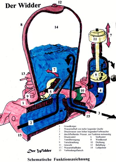
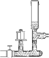
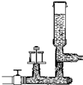
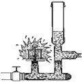
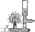
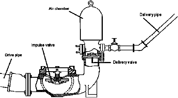
Abbildung 1 veranschaulicht das Prinzip; Zunächst ist das Impulsventil (oder das Ablassventil, da es sich um den nicht gepumpten Wasserausgang handelt) durch die Schwerkraft geöffnet (oder in einigen Ausführungen durch eine leichte Feder offen gehalten) und das Wasser fließt daher durch das Antriebsrohr (durch ein Sieb) ) aus der Wasserquelle. Wenn die Strömung beschleunigt wird, steigen der hydraulische Druck unter dem Impulsventil und der statische Druck im Körper des Hydrams, bis die resultierenden Kräfte das Gewicht des Impulsventils überwinden und beginnen, es zu schließen. Sobald die Ventilöffnung kleiner wird, baut sich der Wasserdruck im Hydramkörper schnell auf und schlägt das Impulsventil zu. Die bewegte Wassersäule im Antriebsrohr kann nicht mehr über das Impulsventil austreten, ihre Geschwindigkeit muss also schlagartig abnehmen; dies verursacht weiterhin einen beträchtlichen Druckanstieg, der das Druckventil zur Luftkammer öffnet.
Sobald der Druck die statische Förderhöhe überschreitet, wird Wasser durch das Förderrohr nach oben gedrückt. In der Luftkammer eingeschlossene Luft wird gleichzeitig auf einen Druck komprimiert, der den Förderdruck übersteigt. Schließlich kommt die Wassersäule im Antriebsrohr zum Stillstand und der statische Druck im Gehäuse sinkt dann bis nahe an den Förderhöhendruck. Das Druckventil schließt dann, wenn der Druck in der Luftkammer den im Gehäuse übersteigt. Nach dem Schließen des Druckventils wird weiter Wasser gefördert, bis die Druckluft in der Luft ist
Abbildung 1: Die Hydraulikkolbenpumpe / Widderpumpe
Die Luftkammer ist eine wichtige Komponente, denn neben der Verbesserung der Effizienz des Prozesses, indem die Förderung nach dem Schließen des Förderventils fortgesetzt werden kann, ist es auch wichtig, die Stöße abzufedern, die ansonsten aufgrund der inkompressiblen Natur des Wassers auftreten würden. Wenn sich die Luftkammer vollständig mit Wasser füllt, leidet nicht nur die Leistung, sondern der Hydramkörper, das Antriebsrohr oder die Luftkammer selbst können durch den resultierenden Wasserschlag brechen. Da Wasser insbesondere unter Druck Luft auflösen kann, besteht die Tendenz, dass die Luft in der Kammer durch Mitreißen mit dem Förderstrom erschöpft wird. Verschiedene Hydram-Designs lösen dieses Problem auf unterschiedliche Weise. Die einfachste Lösung erfordert, dass der Benutzer den Hydram gelegentlich stoppt und die Luftkammer entleert, indem er zwei Hähne öffnet, einen zum Einlassen von Luft und einen zum Ablassen von Wasser. Eine andere Methode bei komplexeren Hydrans besteht darin, ein sogenanntes Schnüffelventil einzubauen, das es automatisch ermöglicht, Luft in den Boden der Luftkammer zu saugen, wenn der Wasserdruck vorübergehend unter den Atmosphärendruck fällt. Bei solchen Geräten ist es wichtig, gelegentlich zu überprüfen, ob das Schnüffelventil nicht mit Schmutz verstopft ist und ordnungsgemäß funktioniert.
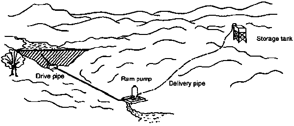
Abbildung 2: Das hydraulische Widderpumpensystem
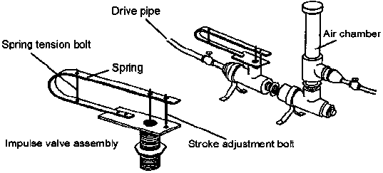
Dieser Zyklus des Hydrams wird durch die Charakteristik des Ablaufventils getaktet. Normalerweise kann er durch eine einstellbare Feder gewichtet oder vorgespannt werden, und im Allgemeinen ist ein einstellbarer Schraubanschlag vorgesehen, der es ermöglicht, die maximale Öffnung zu variieren. Die Effizienz, die bestimmt, wie viel Wasser aus einem bestimmten Antriebsstrom gefördert wird, wird entscheidend von der Ventileinstellung beeinflusst.
Denn bleibt das Ablaufventil zu lange geöffnet, wird ein geringerer Anteil des Durchlaufwassers gepumpt, der Wirkungsgrad sinkt, schließt es zu schnell, baut sich der Druck im Hydramkörper nicht lange genug es wird also wieder weniger Wasser geliefert. Oftmals gibt es eine einstellbare Schraube, die die Öffnung des Ventils auf ein vorbestimmtes Maß begrenzt, wodurch die Vorrichtung gedreht werden kann, um ihre Leistung zu optimieren. Ein erfahrener Installateur sollte in der Lage sein, das Ablaufventil vor Ort einzustellen, um eine optimale Leistung zu erzielen. Daher ist ersichtlich, dass die Leistung eines Hydrams konstant ist und nicht einstellbar ist. Ein Vorratstank ist normalerweise am oberen Ende der Förderleitung enthalten, um je nach Bedarf Wasser in variablen Mengen entnehmen zu können.
Installation requirements
Figure 2 illustrates a typical hydram installation, pumping water to a small storage tank on a plateau. It can be seen that the supply head is created in this case by creating a weir. In some cases a small stream is diverted to provide the water supply.
Where greater capacity is needed, it is common practice to install several hydrams in parallel. This allows a choice of how many to operate at any one time so it can cater for variable supply flows or variable demand. The size and length of the drive pipe must be in proportion to the working head from which the ram operates. Also, the drive pipe carries severe internal shock loads due to water hammer, and therefore normally should be constructed from good quality steel water pipe. Normally the length of the drive pipe should be around three to seven times the supply head. Ideally the drive pipe should have a length of at least 100 times its own diameter. The drive pipe must generally be straight; any bends will not only cause losses of efficiency, but will result in strong fluctuating sideways forces on the pipe which can cause it to break loose.
The hydram body requires to be firmly bolted to a concrete foundation, as the beats of its action apply a significant shock load. The hydram should be located so that the waste valve is always located above flood water level, as the device will cease to function if the waste valve becomes submerged. The delivery pipe can be made from any material capable of carrying the pressure of water leading to the delivery tank. In all except very high head applications, plastic pipe can be considered; with high heads, the lower end of the delivery line might be better as steel pipe. The diameter of the delivery line needs to allow for avoiding excessive pipe friction in relation to the flow rates envisaged and the distance the water is to be conveyed. It is recommended that a hand-valve or check-valve (non-return valve) should be fitted in the delivery line near the outlet from the hydram, so that the delivery line does not have to be drained if the hydram is stopped for adjustment or any other reason. This will also minimise any back flow past the delivery valve in the air chamber and improve efficiency.
Choice of hydram design
Traditional hydram designs, such as in Figure 3, developed a century ago in Europe, are extremely robust. They tend to be made from heavy castings and have been known to function reliably for 50 years or more. However, although a number of such designs are still manufactured in Europe and the USA in small numbers, they are relatively expensive, although generally speaking the drive-pipe, delivery pipe and civil workings will be significantly more expensive than even the heaviest types of hydram.
Lighter designs, fabricated using a welded sheet steel construction, were developed first in Japan and are now in production in other parts of SE Asia including Taiwan and Thailand. These are cheaper, but only likely to last a decade or so as they are made from thinner material which will eventually corrode. Nevertheless they offer good value for money and are likely to perform reliably.
Hydrams are mostly intended for water supply duties, in hilly or mountainous areas, requiring small flow rates delivered to high heads. They are less commonly used for irrigation purposes, where the higher flow rates required will usually demand the use of larger sizes of hydram having 6-inch or 4-inch drive pipes. Manufacturers usually describe the size of a hydram by the supply and delivery pipe diameters (generally given in inches even in metric countries because of the common use of inch sizes for pipe diameters); eg a 6 x 3 hydram has a 6-inch diameter drive pipe and a 3-inch diameter delivery pipe.
Some simple designs that can be improvised from pipe fittings have also been developed by aid agencies (Figure 4), and some interesting versions have also been quite crudely improvised using scrap materials, such as a unit which is being produced in some numbers in southern Laos from materials salvaged from bombed bridges and using old propane cylinders for the air chamber. Needless to say, such devices are very low in cost but the pipes in the end cost considerably more than the hydram. They are not always as reliable as traditional designs, but are usually acceptably reliable with failures separated by many months rather than days, and are easy to repair when they fail.
Performance characteristics
Table 1 indicates estimated performance for typical 4-inch x 2-inch and 6-inch x 3-inch commercial hydrams.
|
Hydram size in inches |
4" X 2" |
| ||||||
|
Head Ratio |
5 |
1015 |
20 |
5 |
10 |
15 |
20 | |
|
Driven flow (litres/sec) |
8.96 |
9.7 |
10 |
9.02 |
20.2 |
17.2 |
17.1 |
19.3 |
|
Delivery (m3/day) |
94 |
51 |
35 |
23 |
216 |
101 |
69 |
50 |
Table 1: Estimated performance of hydrams
Costs
The costs of commercial hydrams are typically in the range from about £1500 for small 2-inch drive pipe sizes up to as much as £5000 for 4-inch or 6-inch sizes. The cost of the drive pipe can also be quite high for the larger sizes. Therefore hydrams are best suited to relatively low flow rates and high head applications.
Of course there are no fuel costs and negligible maintenance costs associated with hydrams.
Further information
References
• Jeffery, T D, Thomas T H, Smith A V, Glover, P B, Fountain P D Hydraulic Ram Pumps: A guide to ram pump water supply systems - IT Publications, 1992
• Iversen H W 'An Analysis of the Hydraulic Ram' - Journal of Fluids Engineering, Transactions of the American Society of Mechanical Engineers - June 1975.
• Kindel E W 'A Hydraulic Ram for Village Use' - Volunteers in Technical Assistance, Arlington, VA, USA - 1970 and 1975.
• Hofkes and Visscher Renewable Energy Sources for Rural Water Supply in Developing Countries - International Reference Centre for Community Water Supply and Sanitation, The Hague, The Netherlands - 1986.
• Watt S B A Manual on the Hydraulic Ram for Pumping Water - ITDG Publishing, 1975.
Suppliers
Note: This is a selective list of supplies and does not imply endorsement by Practical Action.
|
Green and Carter Rams |
John Blake Ltd. |
|
Vulcan Works |
P.O.Box 43 |
|
Ashbrittle |
Royal Works |
|
Wellington |
Atlas Street |
|
Somerset |
Clayton Le Moors |
|
TA21 0LQ. |
Lancashire, BB5 5LP |
|
United Kingdom |
United Kingdom |
|
Tel: +44 (0)1823 672365 |
Tel: 01254 235441 |
|
Fax: 01254 382899 | |
|
Website: http://www.allspeeds.co.uk |
Useful Addresses
Development Technology Unit (DTU)
School of Engineering
University of Warwick
Coventry CV4 7AL
United Kingdom
Tel: +44 (0)1203 522339
Fax: +44 (0)1203 418922
Website: http://www.eng.warwick.ac.uk/DTU
http://www.eng.warwick.ac.uk/DTU/pubs/lift.html
Development Technology Unit who has carried out a lot of research into simplifying the construction of hydraulic ram pumps. The DTU is a research unit within the School of Engineering at the University of Warwick in the UK. The aim of the DTU is to research and promote appropriate technologies for application in Developing Countries.
WOT - Werkgroep Ontwikkelingstechnieken
Working Group on Development Techniques
Vrijhof 205/206
P.O.Box 217
7500 AE Enschede
Netherlands
Tel: +31 53 489 3845
Fax: +31 53 489 2671
Website: http://www.wot.utwente.nl
WOT is a non-profit organisation working in the field of small-scale sustainable energy, based at the University of Twente, Netherlands.
References and further reading
This Howtopedia entry was derived from the Practical Action Technical Brief Water.
To look at the original document follow this link: http://www.practicalaction.org/?id=technical_briefs_water
http://en.wikipedia.org/wiki/Hydraulic_ram
Useful addresses
Practical Action
The Schumacher Centre for Technology & Development, Bourton on Dunsmore, RUGBY, CV23 9QZ, United Kingdom.
Tel.: +44 (0) 1926 634400, Fax: +44 (0) 1926 634401
e-mail: practicalaction@practicalaction.org.uk
web: www.practicalaction.org

Related Articles
- How to Build Human-Powered Water-Lifters
- How to Build an Underground Brick Dome Water Tank
- How to Make a Hand Pump
- How to Make a Solar Pump
- How to Make a Hydraulic Ram Pump
- How to Build a Windpump (Principles)
- How to Use Diesel Engines
- How to Use Photovoltaic Energy
- How to Use Sun Power
- How to Use the Porous Clay Pots and Pipes System
- Micro Irrigation
Deeplink:
http://en.howtopedia.org/wiki/How_to_Make_a_Hydraulic_Ram_Pump
